ESP32 Enclosure
I mentioned in my previous post an interest in getting other interesting artifacts embedded in these pages, and here’s my chance with an STL file. This was a lot harder than expected and involved learning a little bit about Three.js, adding some JavaScript to my assets directory, and adding an HTML file to my _includes directory. Now that it works, though, it will be easy to include other STLs again.
Background
Anyone who plays with hobby electronics knows about Arduino microcontrollers, and after about two sketches (one of which is Blink*), they start wondering, “What about WiFi?”, and discover the ESP32. It’s a great little chip, and many others can espouse its benefits better than I, but two years ago, my dad’s friend came up with a challenge for me. He wanted something that could message him whenever his sump pump came on. I may write more about it later, but to help fulfill his request, I decided to find an ESP32 board with screw terminals*. I ended up purchasing these from Amazon, but the exact same ones can be had from elsewhere, probably for less.
Just Encase
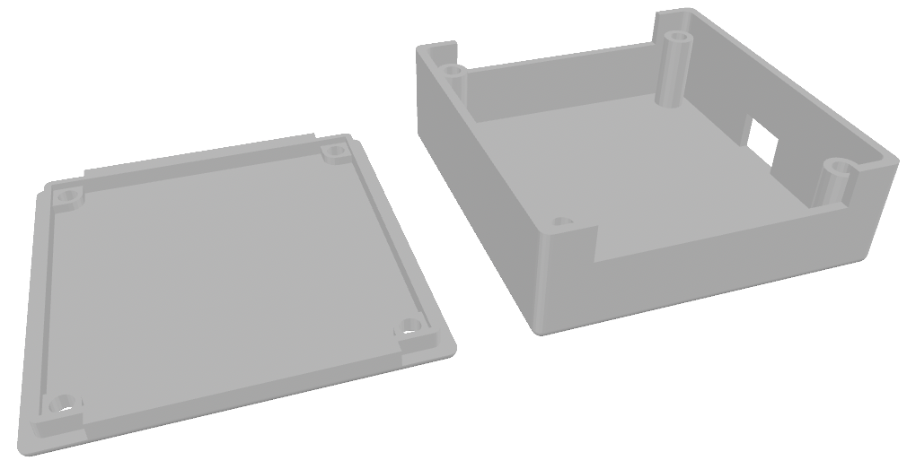
To be a little fancier, and to give a semblance of protection and dignity to the electronics, I decided that they deserved an enclosure. I didn’t find any for sale, so that meant potentially 3D printing one. Thankfully I can do so cheaply and easily via my local library. Not finding one for download*, either, meant I’d be designing my own. I’d used AutoCAD a bit back in college, but that license was long gone. As it turns out, Autodesk has another product called Tinkercad that lets you do 3D modeling (and other things) online. After measuring the dimensions of the board, envisioning how I wanted to have the 3D structure work with a body and lid that could be easily printed, and a bit of tinkering, I came up with this design that I now offer to you.
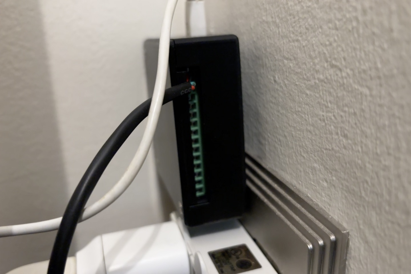
The larger piece has room for the ESP32 chip itself and cutouts for wires to reach the screw terminals, as well as for a micro-USB cable to serve as the power supply. The terminal block board sits perfectly into the the smaller piece (some slight filing of the corners may be required) and is tightly sandwiched between the two.
Assembly
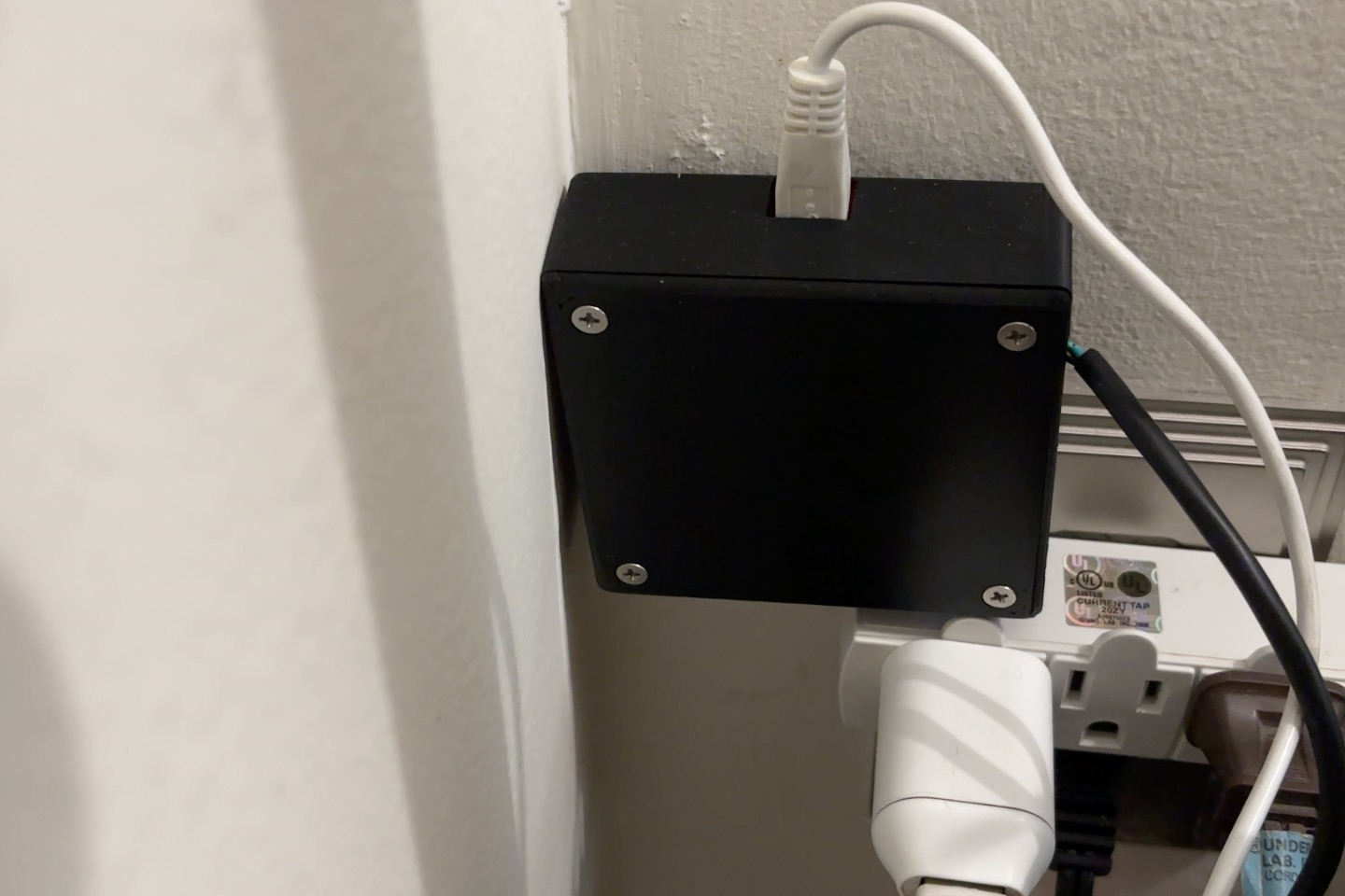
Once printed, assembly is pretty easy. I have a heat set insert tip for my soldering iron and some M3 inserts that I melted into place. Then any desired peripherals can be screwed into the terminal blocks, the board set upside down in the upper piece, and and the lower piece screwed on with some flat head M3 screws. Be sure that you’re satisfied with the sketch that you’re using before assembly, though, as the EN and Boot buttons for flashing become inaccessible. Below you can see an instance of the final product in the real world, currently recording my living room temperature, because I don’t trust my thermostat (more to come on that).